Airbus A320NEO
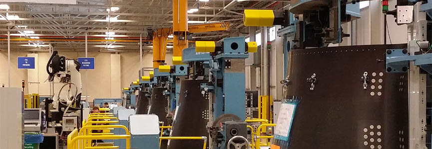
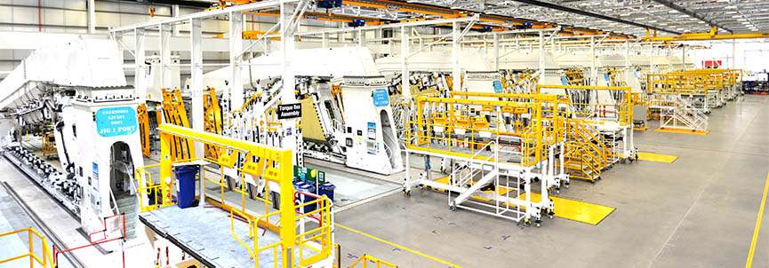
In support of their A320neo Leap X engine program, Electroimpact was selected to supply a complete assembly line system to Aircelle’s UK Plant in Burnley.
Designed to produce the A320neo IFS (Inner Fixed Structure) assembly at a rate of 50+ units per month, the system consists of 22 (11 Left & 11 Right)
moving fixtures that travel between 10 manual work stations and 1 robotic drilling cell. The fixtures pulse from one station to the next between working
shifts powered by an under-floor drag line system.
At Station 3, the fixtures enter an automated drilling cell featuring Electroimpact’s patented Accurate robot drilling system mounted on our “Flush
Floor” 7th axis. Surrounded by light curtains, this creates an open working environment where staff and robot can work safely alongside one another
bringing the best of Automation & the manual dexterity of a human operator together. The standard robot drilling end effector was customized to cope
with the challenging geometry of the IFS and the drilling of “Aluminum Honeycomb” material as part of a CFRP/Aluminum stack.
The Accurate robot was selected by Aircelle for its global positioning accuracy of +/-0.2mm which allows the IFS to be drilled without the need for
on part datuming, every IFS component is drilled relative to markers on the jig itself allowing 100% of the holes to be drilled automatically.
This job highlights the advantages of designing Automation & tooling as one right from the kick off meeting – a belief which is core to Electroimpact’s
design philosophy.
Airbus A350
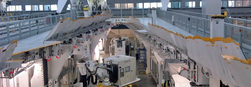
Electroimpact have supplied a complete turnkey factory solution for the manufacture of Airbus’s A350 aircraft wing. The facility, located in Broughton, North Wales UK, is purpose built for the assembly of Airbus’s first commercial carbon fibre composite wing.
Electroimpact proposed the overall factory layout and multiple assembly station designs involving flexible automation solutions.
The initial static wing build jigs assemble the 33m wings horizontally oriented.
The jigs were initially commissioned for full assembly of a wing in a single jig, with scope to allow phased production rate increases as further project construction continued and additional jigs were gradually incorporated to separate the major assembly stages into process specific jigs.
This gives the assembly line flexibility to adapt to changes in production rate.
The modern production solution provided by Electroimpact involves the ‘pulsing’ of full size wings in semi assembled states along a production line. The cells are configured to maximise Electroimpact’s automation solutions.
Electroimpact provided cell transferable robotic drilling machines that can be deployed to primary assembly cells to tack the wingbox. The pulse movement of the wingbox along the production line sees automation specific cells highly utilize large gantry drilling and slave fastener insertion machines capable of drilling Carbon-Aluminium-Titanium components.
The machines can work together to concentrate the drilling and slaving of thousands of holes on both upper and lower wing surfaces.
The provision of configured cover handling frames allows for rapid transfer of large components from differing aircraft variants to and from specific assembly stations quickly.
Worker safety and access has been optimised through the horizontal approach by reducing fall from height risk. The spread of intelligently designed platforms and staging provide efficient ergonomic worker access and welfare.
Airbus A380
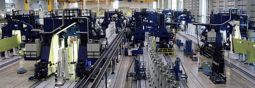
Electroimpact supplied the Outer Wingbox Assembly Line for the Airbus A380 widebody aircraft. This system
consists of four Wing Major (Stage 01) Jigs, each of which holds both a port and a starboard wing. The wings
are built in the vertical orientation. The Stage 01 jigs include dedicated lifting systems to bring the
spar assemblies into the jigs. The spars assemblies are handed off to flags which index the spars via the
hingelines. Ribs are loaded via mechanical assistance devices which pick up the ribs via strongbacks to
avoid damage to the ribs. Rib posts are drilled off manually. The dedicated lifting systems then bring in
the skin panel assemblies.
Five levels of scaffolding integrated with the jig structure provide worker
access to the wing panel surface on both the top and bottom wing surfaces. An innovation is the use of integrated
automatic drilling machines for skin to spar and skin to rib foot drilling as well as for drilling off the
splices. The automated drilling machines move along rails integrated with the jig structure on each level
and can move from surface to surface and jig to jig via machine transport equipment integrated with the jig
structure and scaffolding. This ensures high utilization of the automated equipment while enabling excellent
worker access via the scaffolding. Very large holes for the landing gear attachment points on the rear spars
are drilled using automated machines which are also able to move between jigs. Final fasteners are installed
manually following the automated drilling. The completed wings are removed via the factory overhead crane.
Airbus A400m
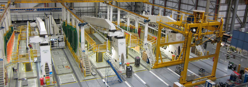
The A400M Wing assembly System contains six large static assembly jigs and two Electroimpact CAWDE Drilling machines.
The drilling capacity is exploited to its full potential using a stand-alone gantry transporter that enables the CAWDE’s
to be picked up and placed on any of the wings surfaces on all the jig cells. The CAWDE machines supports the requirement
to reach the entirety of both wing surfaces and can drill holes up to 1" diameter in deep carbon/titanium stacks.
Each wing assembly cell contains a dedicated assembly jig with a number of unique features that were developed to support
the assembly of this very large carbon fiber wing box. These include, vacuum clamping for the front spar, translating
root end tooling and a rear spar tooling beam that slides open to allow the wing to be unloaded vertically from the jig.
The assembly cells also contain all required worker access, this includes hydraulic lift platforms that retract fully
into the floors when not required. Each wing assembly cell also contains integrated panel deburr zones, and all required
handling equipment for loading spars, ribs and skin panels.
- Fully automatic CNC control and data collection
- 5-axis positioning within the entire wing skin envelope, 30m x 5m x 1m
- Machine transporter to move the machine from jig to jig
- Servomotor/ball screw joint pressure from 900-9000N (approx 200-2000lbf) during drilling and fastening
- Drilling and countersinking holes for 1/4” to 3/4” diameter bolts through multi material stacks of carbon fiber, aluminum, and titanium
- Automated hole diameter measurement of 1/4” to 5/8” diameter holes
- Automatic detection of manually installed slave bolts prior to drilling
- Automatic insertion of 1/4” to 5/8” diameter slave dowels for temporary fastening during the build
- Space on the process shuttle table for a future process tool
Bombardier C-Series
The C-series Wing assembly System comprises an array of ten assembly cells each with a large static assembly
jig integrated with three Lean Technology Drilling machines (LTD). The LTD design is developed from the
Electroimpact CAWDE and has the drilling head placed centrally on a twin tower motion platform. The LTD’s
can be operated on any on the wing assembly cells and are moved between them as required using a dedicated
machine transfer crane. The LTD design supports the requirement to drill holes up to 1" diameter in deep
carbon/titanium stacks on both the front and rear spar areas of the C-series wing.
The LTD machines have a drilling envelope of 3m x 17m and have all the usual features available in E.I.
multifunctional drilling heads such hole probing and stack thickness detection. They also include a tool
swapper for large diameter drill and reaming operations and feed/drive system for single sided slave fasteners.
The open center structure of the machines allow for full all around access to the head for maintenance but
also allows the rear of the head and vertical axes to be enclosed for safety.
Each wing assembly cell is 13m x 36m and contains a dedicated assembly jig and all require worker access
platforms. The wing assembly cells also contain integrated panel deburr zones, and all the handling means
for loading spar assemblies, ribs and skin panels. The finished wing boxes are unloaded from the jig cells
using a custom vacuum lifter which also rotates the wing from the vertical build orientation to flight attitude.
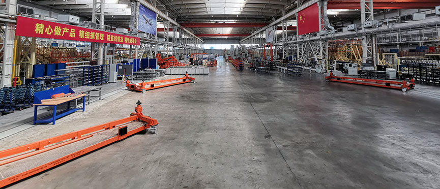
XAC C919
For the COMAC C919, Electroimpact is providing a large-scale turnkey assembly line for building up the outer wings.
Starting from individual component parts, the entire wing is built up from spar subassembly through to finished wing
equipping and testing. Electroimpact’s scope of work includes assembly process design, tooling design, equipment design,
start-up support, and production support through the initial wing builds.
Automation applied to the leading edge spar assembly includes EI’s accurate robot technology, incorporating the latest
nosepiece design to accurately normalize on the high curvature D-Nose skin surface. Drilling on the wing box structure
is performed by the LTD drilling machine, which for this assembly is using an all-new design for automated installation
of temporary bolts on the wing skin.
A tremendous amount of coordination and management is required to develop 19 major workstations in the wing assembly
process, plus many minor subassemblies along the way. Electroimpact has the resources to integrate tooling design, automation
design, material handling, and factory layout while keeping pace concurrently with the aircraft design development.